
Home > Solutions Center > Whitepapers >
Ultimate Guide to Minimum Step Size
Everything you need to know minimum step size.
How is load point minimum step size different than actuation point minimum step size?
Abstract
Minimum step size is a motion system parameter listed on single and multi-axis motion system datasheets. As with many performance specifications, however, minimum step size is a metric based on assumptions and is often mis-represented, as the actual load point location is not considered. Discussed will be terminology definitions and influencing factors, such as design architecture and control approaches, and how accuracy and repeatability play a role.
DEFINITIONS
To properly discuss minimum step size, a common language needs to be established. This section will define terms that will be mentioned throughout this discussion.
Minimum Step Size
Minimum step size is defined as the minimum motion able to be realized by the control system. Results will differ depending on location measured, so a location should be associated with any claim of “Minimum Step Size.”
Noise Floor
Noise Floor for this discussion is the inherent electronic noise of the sensor itself. In the case of an optical, magnetic, inductive, or capacitance encoder, there is error inherent in the optics, interpolation, and any EMI that could be present. In the case of a capacitance sensor, this would be the electronic noise the signal conditioning electronics, primarily the op-amps within the conditioning circuit. This error, or “noise,” would be the sensor output if measuring a perfectly still target.
Static Jitter
Static jitter is the amount of motion that is occurring while the system is not undergoing a move profile. Static jitter in most applications is greater than the noise floor, as it contains both “noise” plus actual motion. It is very common, however, that “noise floor” is incorrectly referenced to mean “static jitter.”
Resolution
Resolution is simply the distance a single encoder count represents. For an analog sensor such as a capacitance probe, this value would be the least significant bit of the analog to digital converter. Generally, this would be 18-20 bits over the full-scale range of the sensor. For systems with incremental encoders, this would be the distance represented by one interpolated encoder count.
Actuation Location
Actuation location is defined as the location of the sensor nearest the force input location.
Load Point Location
Load point location is the motion at, or where, the critical process activity is taking place. This could be several centimeters away from the actuation location.
Repeatability
Repeatability is the measurement of final position, relative to repeated moves into the same location, and not to the commanded position.
Accuracy
Accuracy is the measurement of final position relative to the commanded position.
Controllability and Observability
Controllability is the ability of a servo system to impact the sensor output or a degree of freedom of actuation. Observability is the sensor’s ability to measure motion of one or more degrees of freedom. Having the ability of one, does not guarantee the ability of the other.
Influencing Factors
Design Architecture
At the core of minimum step is the system design. There are many design decisions that directly impact minimum step size, those being the sensor location, force delivery (direct drive versus ball screw, or other), bearing type (cross roller, recirculating, air), and load point offset. Each of these will be discussed in terms of how they impact step size.
I. Sensor Location
Sensor location has the single biggest influence on minimum step size. Designs with only a sensor at the point of force delivery, and not at the load point, have no observability for load point motion. This means load point minimum step size is uncontrolled. Designs with sensors at the load point, however, have the needed observability, and depending on other factors such as force delivery and control scheme, have a good likelihood of reducing the minimum step size.
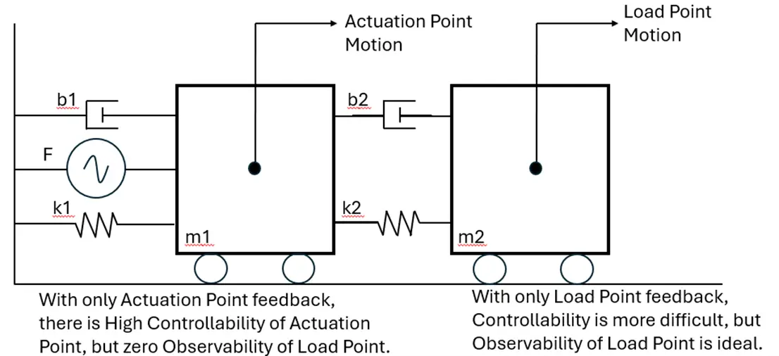
Figure 1: Sensor location impact on Controllability and Observability.
II. Force Delivery
Force delivery plays a significant role in minimum step size. Any system with backlash, or compliance in the force delivery path, independent of sensor location, will adversely impact minimum step size. Designs having backlash and sensors only at the actuation point inherently have larger minimum step sizes at the load point, as any change of direction less than the backlash amount is simply not observed at the load point.
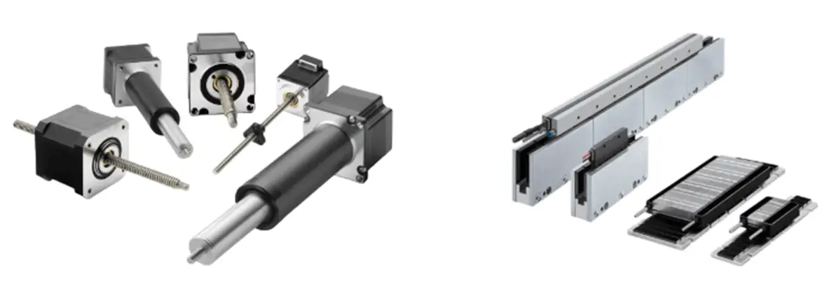
Figure 2: Ball screw versus direct drive option for force delivery. (Ref: Best Motor for Dispensing & Automation: Linear vs Ball Screw).
III. Bearing Type/Friction
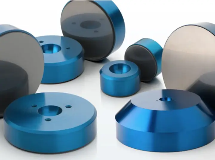
Bearing choices will play a key role in determining how the load point moves. An air-bearing system, for example, will have the best performance, as there are few residual stresses in the air film to impede the load point from following the motion of the supporting mechanics. In contrast, however, there are mechanical bearings such as cross roller and recirculating. Cross Roller bearings have better performance in terms of overall straightness, accuracy and repeatability, versus recirculating, but both are subject to internal stresses held by stiction of the mechanical contact between the ball and rolling surface. These stresses can be very unrepeatable, making movement unpredictable.
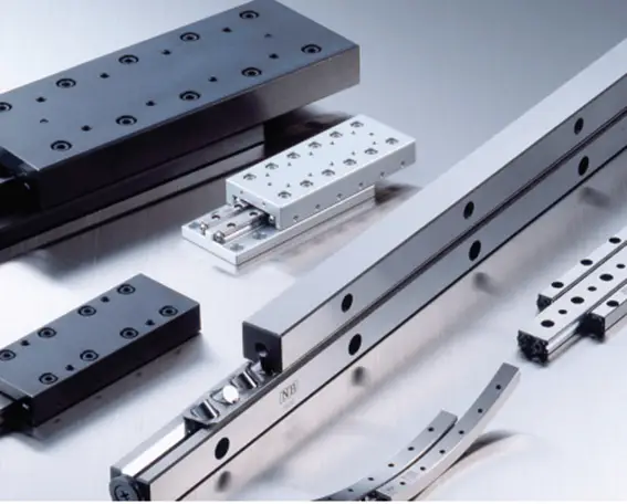
Figure 3: Bearing types that impact minimum step size. (Ref: Air Bearings vs Contact Bearings | New Way Air Bearings)
IV. Load Point Offset
For both air and mechanical bearing architectures, load point offset will impact minimum step size. Load point offset is the moment arm between the load point location and the supporting bearing. The moment created by load acceleration or the force of gravity will produce both static and dynamic deflection, as mechanics are not infinitely stiff, and nanometers of deflection can occur easily during seemingly inconsequential load accelerations. Mechanical stresses between the ball and rail, along with variability in air film tilt stiffness, can cause Abbe error from the offset to vary with location, temperature, and load.
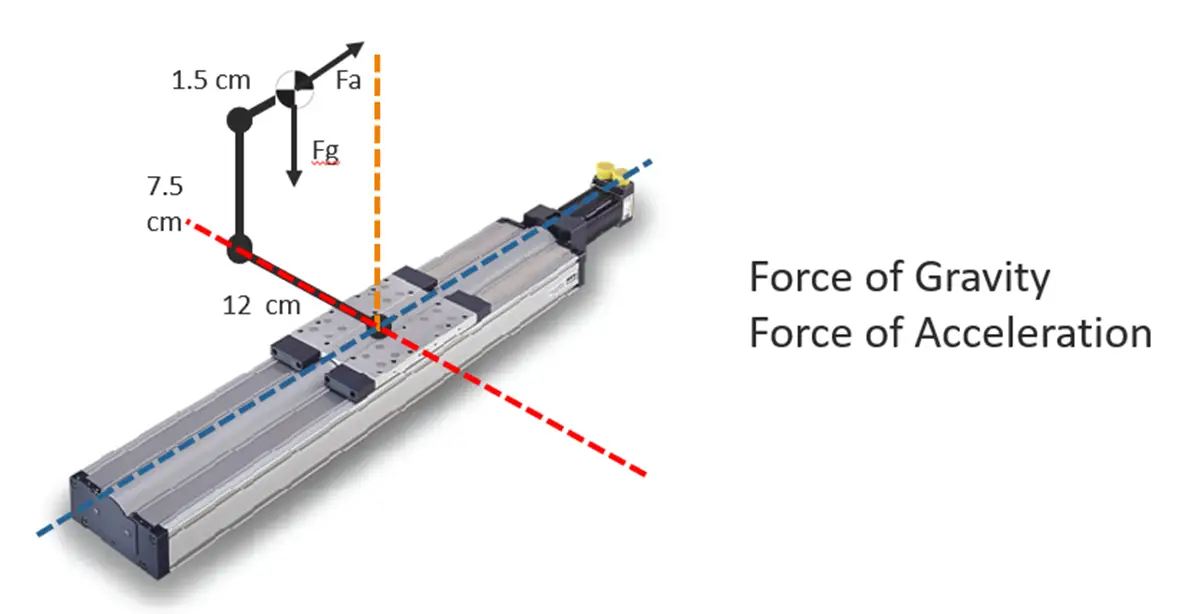
Figure 4: Load Point Offset. (Ref A3 Certified Motion Control Professional Training-Basic Machine Design and Physics of Motion)
Control
Feedback control schemes impact the minimum step size through the influence of integrator gain.The feedback, combined with the plant (mechanics), must have at least one pole in the denominator (an integrator) for a final error of zero to be possible.
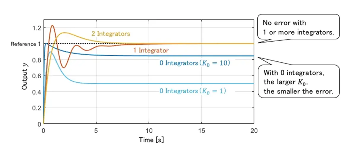
Figure 5: Steady State Error versus Control Design. (Ref: Steady-State Error and Internal Model Principle for Disturbance)
Systems meeting these criteria, but also having backlash, friction, or other compliance in the drive train, may not reach zero steady-state error. “Stiction,” a stick-slip phenomenon, is a good example that is prevalent in all mechanical bearing systems. In these cases, a “deadband” control scheme might be implemented, which will adversely impact the minimum step size directly, but solves the “stick-slip” control challenge integrator gains create. The dead band algorithm shuts off the output when the system is within a position window. Once outside that window, the control effort is resumed. As mentioned, this approach will eliminate the stick slip behavior, but at the cost of never landing at the commanded location and worsening the minimum step size performance.
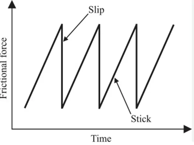
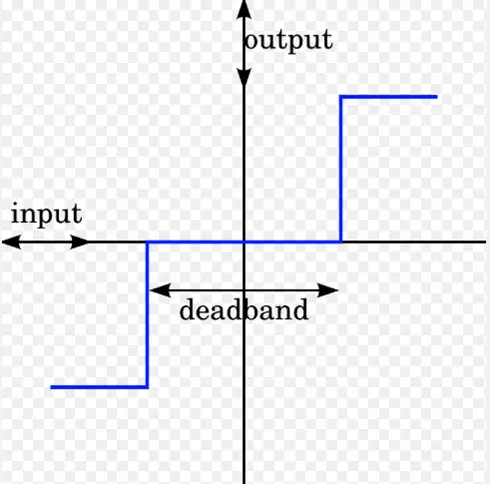
Figure 6: Stick-Slip Phenomenon and Deadband. (Ref: Processing method utilizing stick-slip phenomenon for forming periodic micro/nano-structure - ScienceDirect, Deadband - Wikipedia)
Accuracy, Repeatability, Resolution, and Minimum Step Size
Resolution is sometimes stated as minimum step size, and although at a high level, this might make sense, the reality is that although this could be true at the actuation point location, it
is rarely met at the load point location.
In every motion system, accuracy and repeatability specifications at the load point are significantly larger than resolution. As an example, a system with 5 nm of encoder resolution might have an accuracy of 0.5 um and repeatability of 30 nm. These numbers are vastly larger than the resolution, bringing the question of “what matters to the system?”
Now let’s consider how minimum step size and repeatability are related. What if the minimum step size were not repeatable? If you moved, and then moved back the same amount, what if the final position were not as expected?
This is an interesting and real consideration, which leads to the question: if the system’s minimum step size is not repeatable, does it matter to specify this parameter at all? In this context, a good argument can be made that a step or movement does not necessarily have to be accurate, but it must be repeatable. For the step to have a useful outcome, if you step forward, then backward, you must arrive at the same place. With repeatability often larger by 5 to 10 times resolution, one can see resolution is a poor value for minimum step size when considered at the load point. In contrast, however, repeatability and minimum step size (at the load point) are in fact similar, which makes sense given their definition.
Figure 7 below describes the two situations of minimum step size, those being at the actuation point location and at the load point. At the actuation point, minimum step size and resolution are generally equivalent, while at the load point, repeatability and minimum step size are generally equivalent. Lastly, these two numbers (minimum step size at the load point and actuation point) could be different by a factor of five.
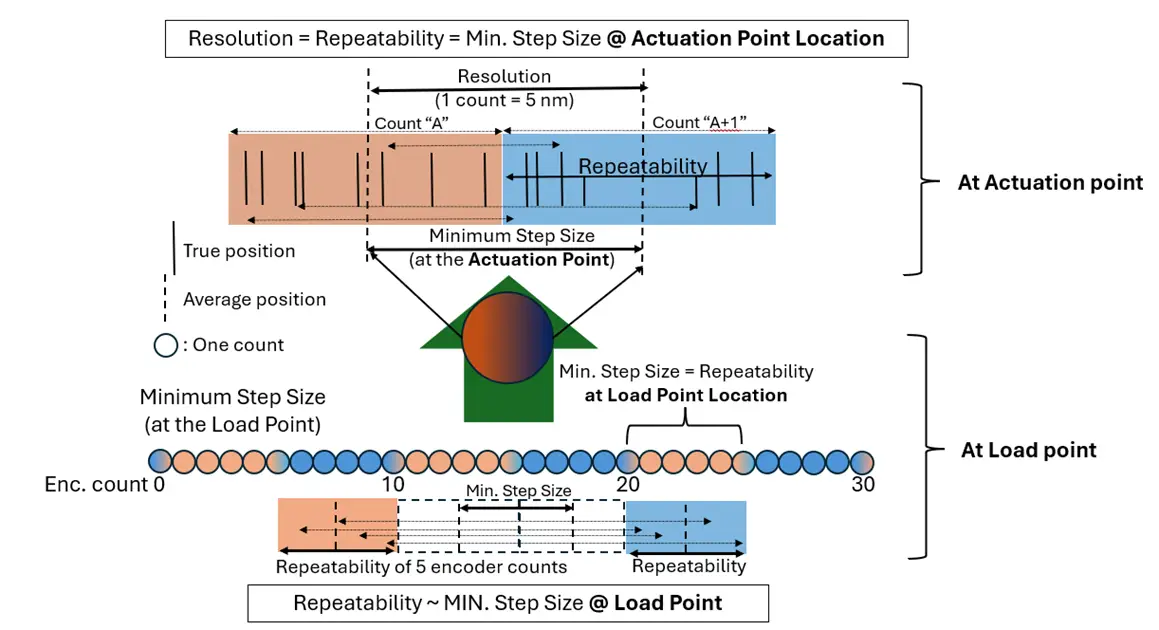
Figure 7: Repeatability versus accuracy versus resolution and minimum step size.
Measurement
Equipment/Setup
Measuring the minimum step size can be very simple to modestly complex. Collecting encoder data is generally very simple, as the servo drive will have a data recording feature and final position can be recorded over time. Load point measurement, however, can become far more complicated as capacitance probes or laser interferometer tooling will be needed. Fixturing of the reflective component for the interferometer and capacitance probes will add to the measurement output, so care must be taken to keep mass low as to not alter center of gravity locations, while maximizing stiffness to reduce deflection. When using an interferometer, “air-wiggle” can be a huge component of the measurement, so accommodations in the setup or processing should be made to reduce or eliminate the air influence. For both load point and actuation point measurements, thermal drift will impact the outcome, so a temperature-controlled environment is needed.
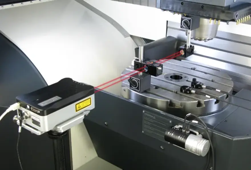
Figure 8: Laser interferometer setup. (Ref: An Introduction To Interferometers For Highly Accurate Engineering Measurements - Engineering.com)
Processing
I. Techniques
Post processing data from both load point and actuation point locations will be needed as static jitter will always be larger than the minimum step size. The most common processing technique is a rolling average, which is a low pass filter, removing the high frequency jitter component of the signal. The averaging technique reduces both electrical noise and jitter vibration amplitude, though it is not always appropriate to disregard these factors when assessing minimum step capability.
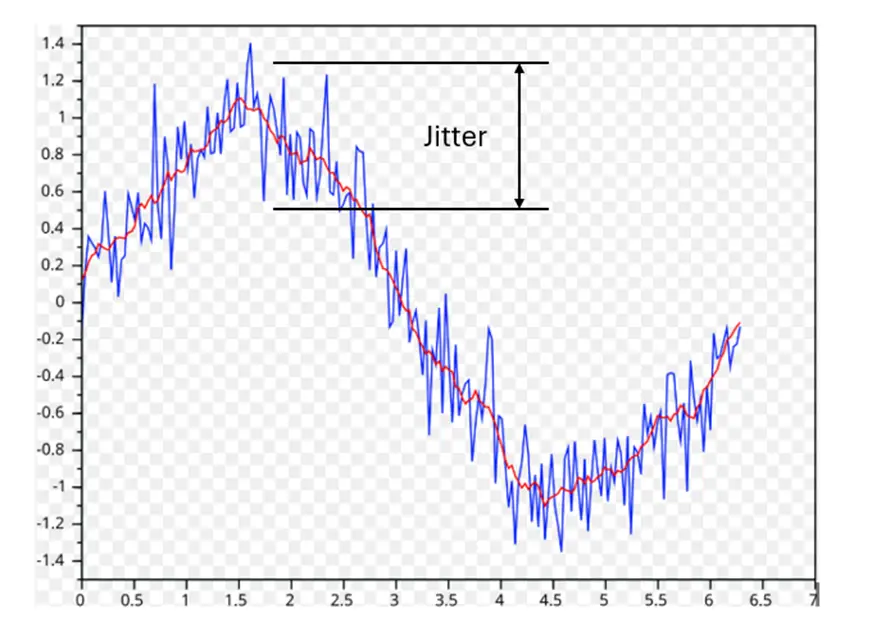
Figure 9: Moving average filter. (Ref: Moving Average - Wikipedia)
II. When to Filter and When Not?
The decision to average data, or not, can be difficult to make, so here are some basic guidelines and facts. First, all data has jitter. How we treat is dependent on the question being asked. If the imaging is sensitive to velocity, meaning a pixel will “smear” across the field of view or TDI (Time Delay Integration), then the actual jitter amplitude should be measured correctly. In this case, no filtering or averaging should be done. If, however, motion is commanded to center an object in a field of view, or to make an angular correction for orthogonal purposes, then the actual jitter amplitude is inconsequential, and averaging could or should be used to characterize the performance of the system. Often, looking at raw data complicates the outcome, making what is important difficult to quantify.
Below are three examples of what a minimum step could look like, those being raw data, lightly averaged, and heavily averaged. The heavily averaged data clearly shows the step increment, while the raw average does not. While all these datasets could be used as evidence of a minimum step, the application will ultimately determine which level of filtering is appropriate. It should be noted that if the position data is used in any closed loop, minimum to no averaging should be done, as averaging causes time delays and limits system performance.
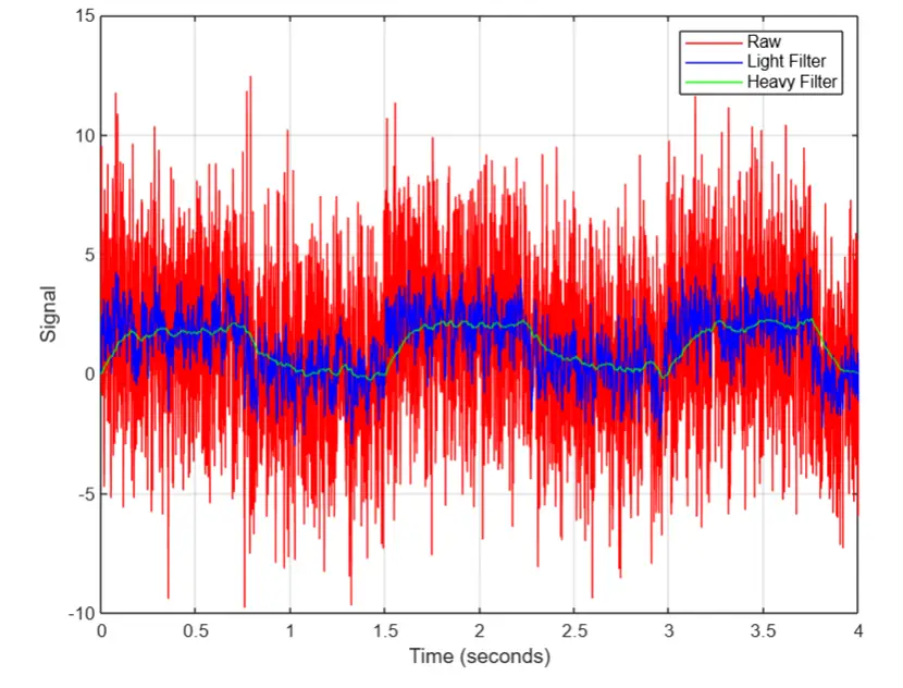
Figure 10: Minimum step size shown with averaging versus no averaging.
CONCLUSION
Any minimum step size specification should be associated with location. Two choices can be made, those being the load point (most representative) and actuation point (less representative, but worth knowing). In both cases there are many influencing factors, including the sensor location, force delivery, bearing type, control strategy, and load point offset. Each of these will play a role, varying in degrees of importance, depending on whether the system is supported by air or a mechanical bearing. With each of these factors being a variable, the one constant is the interpretation of Repeatability versus minimum step size. If a system has a repeatability larger than the stated minimum step size, one could rightly question whether that makes sense, as there is often an expectation that a minimum step size should, by definition, be repeatable. Care should be taken to understand the assumptions made, and most importantly, the location associated with the stated minimum step size. In most applications, minimum step size at the load point location will be larger than that at the actuation point, with a value of three to five times the resolution.

NEED SUPPORT UNDERSTANDING MINIMUM STEP SIZE?
Contact Allient for support in understanding minimum step size.